Difference between revisions of "Disaster-Preparedness"
Jump to navigation
Jump to search
(→Accelerometer) |
|||
| Line 81: | Line 81: | ||
===Accelerometer=== | ===Accelerometer=== | ||
====Use==== | ====Use==== | ||
| − | * | + | * It didn't fit on the normally sized breadboard so we ran power/ground underneath and used the one available row for the xyz/sleep pins. This was a non-issue on the prototype board. |
| + | * There are existing code libraries but we didn't use them. They can be found [[https://virtuabotix-virtuabotixllc.netdna-ssl.com/core/wp-content/uploads/2011/10/Accelerometer_1S1A.zip here]] with examples. We could still use this library to setup the accelerometer, but I've written my own library for reading values and would prefer to use that. | ||
* Noise was an issue, but the noise was reduced considerably when using a prototype board instead of a breadboard. | * Noise was an issue, but the noise was reduced considerably when using a prototype board instead of a breadboard. | ||
====Wiring==== | ====Wiring==== | ||
| − | * Power, ground, xyz, and sleep. Pins are labeled. | + | * Power, ground, xyz, and sleep. Pins are labeled on the device. |
| − | * | + | * The device uses Arduino's pullup resistors, so no external resistors are required. |
| − | * | + | * xyz is analog and sleep is digital. |
====Code Sample==== | ====Code Sample==== | ||
| + | Using existing libraries, | ||
<pre> | <pre> | ||
| − | + | #include "Accelerometer.h" | |
| − | |||
| − | void setup() { | + | Accelerometer acc = Accelerometer(); |
| − | + | ||
| + | void setup() | ||
| + | { | ||
| + | Serial.begin(9600); | ||
| + | |||
| + | // SL GS 0G X Y Z | ||
| + | acc.begin(3, 4, 5, A0, A1, A2); | ||
| + | |||
| + | //calibrate for a start position | ||
| + | Serial.println("Please place the Accelerometer on a flat\nLevel surface"); | ||
| + | delay(2000);//Give user 2 seconds to comply | ||
| + | acc.calibrate(); | ||
} | } | ||
| − | void loop(){ | + | void loop() |
| − | + | { | |
| + | delay(2000); | ||
| + | acc.read(); | ||
| + | Serial.print(acc._Xgs); | ||
| + | Serial.print("x, "); | ||
| + | Serial.print(acc._Ygs); | ||
| + | Serial.print("y, "); | ||
| + | Serial.print(acc._Zgs); | ||
| + | Serial.println("z"); | ||
} | } | ||
</pre> | </pre> | ||
Revision as of 22:04, 6 June 2014
Motion Sensor
Under construction until the end of Fall 2014 semester unless indicated otherwise.
Purpose
- Detect and measure motion.
- Use multiple cheap, inexpensive sensors to increase accuracy/reliability/functionality.
- Be cheap and portable.
- Provide data that can be aggregated over a network.
Sensors
- We used tilt switches, a piezo element, a laser / photoresistor combo, and an accelerometer.
- We specified thresholds for each
Tilt
Use
- A tilt switch uses a material to complete a circuit (E.G. press a button) when it reaches either end of the container.
- We used mercury switches on the X and Z axes.
- The Y axis wasn't very sensitive. It only seemed useful for seeing if the device had flipped over.
- Tilt switches work best when the motion is parallel to them. This loss of resolution can be minimized by adding more sensors at half-steps. For example, we could add two tilt in-between XZ to measure diagonal motion more effectively. (add a picture)
- We looked exclusively for change. This means we didn't care about what state the tilt switch was in, just if it had changed since the last read.
- We averaged readings so that lots of activity in a small time frame would be easier to recognize.
- Noise isn't an issue.
Wiring
- Power, ground, and signal.
- 10k resistor on power.
- Signal is digital.
Code Sample
const int tiltPin = 2;
int tiltState = 0;

void setup() {
  pinMode(tiltPin, INPUT);
}

void loop(){
  tiltState = digitalRead(tiltPin);
}
Resources
- [wikipedia]
- [useful code]
Piezo Element
Use
- A very cheap, diverse piece of kit.
- Can be used as a button, a knock sensor, to detect vibration, to detect sound, or to produce sound similar to a buzzer.
- We used it as a vibration sensor.
- Vibration sensitivity is increased dramatically when the piezo element is attached to a solid object by a weight, glue, or tape.
Wiring
- Signal and ground. Signal serves as power.
- 1k resistor on the signal; 10k worked similarly, so 1k+ is probably fine
- analog
- minimal noise
Code Sample
const int piezoPin = 2;
int piezoState = 0;

void setup() {
  pinMode(piezoPin, INPUT);
}

void loop(){
  piezoState = analogRead(piezoPin);
}
Resources
Accelerometer
Use
- It didn't fit on the normally sized breadboard so we ran power/ground underneath and used the one available row for the xyz/sleep pins. This was a non-issue on the prototype board.
- There are existing code libraries but we didn't use them. They can be found [here] with examples. We could still use this library to setup the accelerometer, but I've written my own library for reading values and would prefer to use that.
- Noise was an issue, but the noise was reduced considerably when using a prototype board instead of a breadboard.
Wiring
- Power, ground, xyz, and sleep. Pins are labeled on the device.
- The device uses Arduino's pullup resistors, so no external resistors are required.
- xyz is analog and sleep is digital.
Code Sample
Using existing libraries,
#include "Accelerometer.h"

Accelerometer acc = Accelerometer();

void setup()
{
  Serial.begin(9600);

  //        SL GS 0G X   Y   Z
  acc.begin(3, 4, 5, A0, A1, A2);

//calibrate for a start position
Serial.println("Please place the Accelerometer on a flat\nLevel surface");
delay(2000);//Give user 2 seconds to comply
acc.calibrate();
}

void loop()
{
  delay(2000);
  acc.read();
  Serial.print(acc._Xgs);
  Serial.print("x, ");
  Serial.print(acc._Ygs);
  Serial.print("y, ");
  Serial.print(acc._Zgs);
  Serial.println("z");
}
Resources
Housing
Case
Resonate Frequency
Power
Code
Research
These are notes and observations from research.
Earthquake
- occur due to movement in tectonic plates
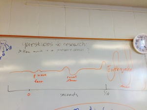
- only seconds of notice, 5-10 seconds
- [p waves] are much faster than [s waves] and the actual waves that cause the earthquake.
- earthquakes travel at about the same speed as data networks
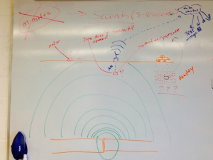
- can be measured by motion (on surface or underground) and pressure (underground)
- downside of underground monitoring is 1) power and 2) transmission
- can use repeaters or solar power to solve these issues
- advantage of being underground is distance from noise (such as animals and humans) and being closer to the source of the earthquake
- being attached to rock is good
- downside of underground monitoring is 1) power and 2) transmission
Resources
Tsunami
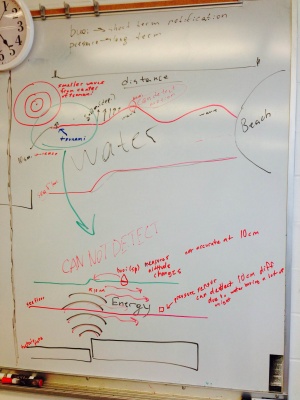
- in the deep sea pressure sensors are used to measure the relatively small sea-level change (in centimeters)
- nearer to shore, where waves start to form, altitude could be measured by buoy
- travel at hundreds of miles per hour
- tsunami headquarters in Hawaii
- notification could be minutes to hours in advance depending on distance from source of tsunami
- height/speed of wave reduces with distance


