CS382:Software
Contents
Software
End-Notes
Predator Prey ( Lynx Hare )
- Wolf Sheep Agent based netlogo model
- This can be run in a browser on Firefox.
- Wolf Sheep Systems Dynamics netlogo model
- Same for this.
<font color
Foundations of Modelling
Firefox
Visualization
- Spreadsheet software.
- Web browser.
- Access to IPUMS.
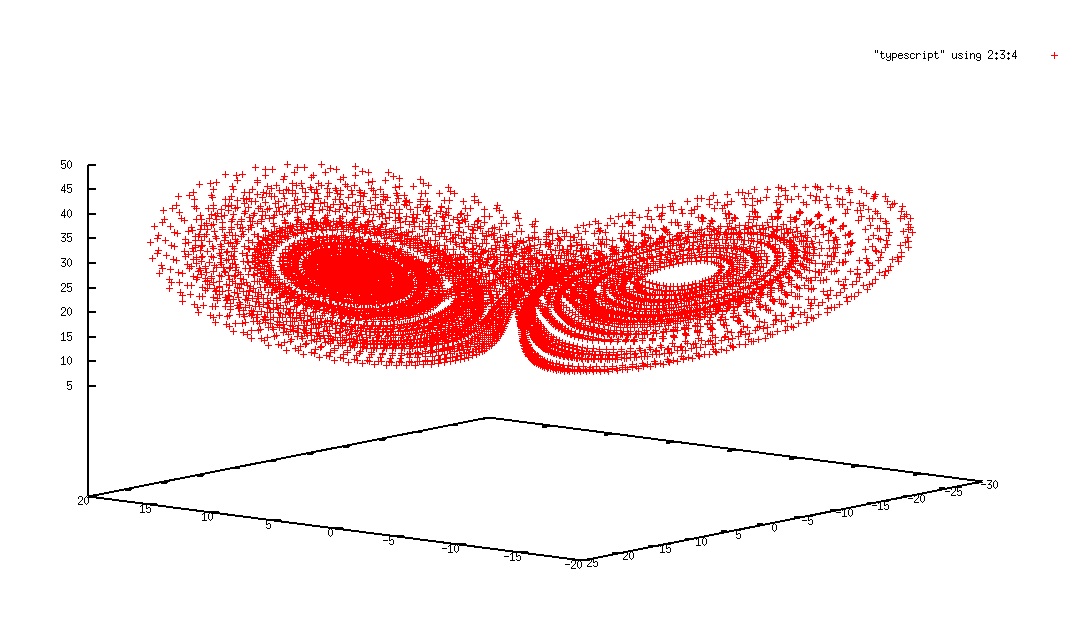
<Chaos>
- Lorenz attractor in 3D
- The c source code generates values in 3 dimensional coordinate.
- Students can generate infinite patterns of values by changing 3 parameters in 3 non-linear differential equations.
- The values can be plotted with GNUplot like this picture.
- There is the source code of Lorenz attractor for second life, but it includes numbers of bugs.
- Excel for statistical computation
- [http://answers.yahoo.com/question/index?qid
Rocket Modeling
- RocketModeler II
http://www.grc.nasa.gov/WWW/K-12/rocket/rktsim.html
With this software you can investigate how a rocket flies by changing the values of different design variables.
GENERAL INSTRUCTIONS
If you see only a grey box at the top of this page, be sure that Java is enabled in your browser. If Java is enabled, and you are using the Windows XP operating system, you may need to get a newer version of Java. Go to this link: http://www.java.com/en/index.jsp, try the "Download It Now" button, and then select "Yes" when the download box from Sun pops up.
This program is designed to be interactive, so you have to work with the program. There are several different types of input "widgets" which you use to send information to the program to change the analysis and display results:
1. Some of your selections are made by using a choice box. A choice box has a descriptive word displayed and an arrow at the right of the box. To make a choice, click on the arrow, hold down and drag to make your selection from the menu which is displayed.
2. Some selection are made by using the buttons on the panels. To activate a button move your cursor over the button and click your mouse. The different colored buttons have different effects: -1. Blue buttons are option buttons which you can select. Most option buttons turn Yellow to indicate your current selection. -2. White buttons are processes which you must complete in order to launch your rocket. You indicate that the process is complete by pushing a white "GO" button on an input panel. The process button and the "GO" button turn Green when you are successful. You must have all green buttons in "Mission Control" before you can launch your rocket. -3. Red buttons demand immediate attention or "Aborts" the mission.
3. On each input panel, the current value of a design variable is presented to you in a text box. Different colored boxes have different meanings: -1. A white box with black numbers is an input box and you can change the value of the number. To change the value in an input box, select the box by moving the cursor into the box and clicking the mouse, then backspace over the old number, enter a new number, then hit the Enter key on your keyboard. You must hit Enter to send the new value to the program. -2. A black box with colored numbers is an output box and the value is computed by the program. Red numbers indicate trouble. If the CG or CP output is red, your rocket is unstable and you must change the design. If the Weight output is red, you have insufficient thrust to lift the rocket and you must either decrease the weight or increase the thrust.
4. For most input variables you can also use a slider, located next to the input box, to change the input value. To operate the slider, click on the slider bar, hold down and drag the slider bar, or you can click on the arrows at either end of the slider. If you experience difficulties when using the sliders to change variables, simply click away from the slider and then back to it.
If the arrows on the end of the sliders disappear, click in the areas where the left and right arrow Images should appear, and they should reappear.
SCREEN LAYOUT
The program screen is divided into two main parts:
1. On the left of the screen is the graphics window in which you will see your rocket design, the test flight, and output data. Details are given in Graphics. 2. On the right of the screen are the input sliders and boxes that you use to change your design or to set flight conditions. Details of the Input Variables are given below.
GRAPHICS
You move the graphic within the view window by moving your cursor into the window, hold down the left mouse button and drag to a new location. You can change the size of the graphic by moving the "Zoom" widget in the same way. If you loose your picture, or want to return to the default settings, click on the "Find" button at the bottom of the view window. The grid behind your design is toggled on or off by using the "Grid" button located above the Zoom widget. There are three main graphics displays:
1. During the "Design" and "Fuel" processes you see the design graphics. As you change any input variable, like the tube length or fin geometry, the graphic changes. There are two colored circles on the rocket. The yellow circle is the location of the center of gravity (CG). The black circle is the location of the center of pressure (CP). The location of the CG and CP change during design and fueling. For a stable rocket, keep the CP below the CG. When the white "Fuel" button is pushed, the graphic includes some information about the propulsion system of your rocket. The form of the graphic depends on the type of rocket. 2. During the "Pad" and "Launch" processes the graphic changes to display the flight graphics. The location and orientation of the rocket is displayed during flight, although the rocket is not drawn to scale with the grid and surroundings. After a successful flight you can save the flight trajectory by clicking the "Save" button below the zoom widget. You can save 5 flights for comparisons. During the flight you have two viewing options. The default is the "Tracking Mode" option which keeps the rocket centered in the view window during the flight. The zoom widget is disabled during tracking mode. The other viewing option keeps the view fixed on the ground. The "Find" button takes you to the launch pad. Use the zoom widget and the graphic movement to examine the entire flight trajectory with this option. Viewing options are toggled using the "Track" button located below the graphics window. 3. The blue "Data" button on the "Launch" input panel displays output graphics in the view window. Data is displayed as "strip charts" of thrust, weight, drag, velocity, and height. Depending on the rocket type, some of these variables do not change. The horizontal grid increments are 1 second on the strip charts. You return to the flight mode graphics by clicking the "View" button on the "Launch" input panel.
INPUT VARIABLES
Input variables are located on the right side of the screen. You first select the type of rocket by using the blue buttons at the top of the screen:
1. A Ballistic projectile is an object which has no propulsion system and is shot into the air at some initial velocity. Gravity eventually brings the object back to the surface. Ballistic objects have only one input panel which is located at the lower right. You can select several different types of objects by using the choice box at the upper right of the input panel. A representative weight, cross-sectional area, and drag coefficient (CD) are then loaded onto the input panel. You can reset these values as described above. The launch speed must also be specified before launch. You then click "GO" to complete the design and move to the launch pad. 2. An Air rocket is a special case of a ballistic projectile. The weight of the compressed air rocket is determined by your design and a check is made for rocket stability. The fuel for the air rocket is compressed air. You increase the pressure of the air by using a pump. The program computes the launch speed based on an integration of Newton's second law. The launch speed depends on the length of the launch tube. 3. A Water rocket uses a standard 2-Liter plastic bottle for the body of the rocket. You design the other parts of the rocket, including the nose cone and fins. The fuel for the water rocket is water which is pressurized by an air pump. You specify the amount of water, the air pressure, the diameter of the nozzle and the length of the launch tube. Because water is forced out of the nozzle under pressure, the weight of the rocket changes during the flight. 4. The Solid rocket is powered by a solid rocket engine that you purchase from a hobby store. You design the shape of the rocket and the program checks for stability. You fuel the rocket by selecting the number and type of rocket engine. The thrust characteristics of many types of engines are modeled in the program.
During rocket Design, you have four choices of input panels; Nose, Payload, Body, and Fins. You select the input panel by using the blue buttons located above the graphics window on the left. On each input panel, you select the material for the part being designed by using the choice button at the top of the panel. The density of the material is shown to the left of the choice button and is used in computation of the weight of the part. The weight of the part affects the location of the center of gravity and the stability of the rocket. There are input sliders and boxes on each panel which change the geometry of each part:
1. On the Nose panel, you can select the shape by using the choice box at the top. For each shape, you can change the vertical length of the nose and the base diameter of the nose. The program calculates the area and volume of the nose which is then used in the weight calculation. At the bottom of the Nose input panel, you can select the type of recovery system by using the choice box and you can add ballast weight to the nose to keep CG above CP. When you finish the nose design you can select another part by using the blue buttons, or you can click "GO" to complete the design. 2. The Payload panel is used to design the section between the nose and the body of the rocket. As before, you can vary the length and the diameter of the payload tube. As the payload diameter is varied, the nose diameter is also changed, and the area, volume, and weight of the payload is calculated. On most rockets there is a fairing or transition section between the payload and the body tube. You can vary the length and material of the fairing. When you finish the payload design you can select another part by using the blue buttons, or you can click "GO" to complete the design. 3. The Body panel is used to size the body tube of the rocket. You can specify the length and diameter of the tube for the air rocket and the solid rocket. For the solid rocket, the program insures that the tube diameter is large enough to hold the engine. For all types of rockets you can add a fairing to the bottom of the rocket. The exit diameter of the fairing is the nozzle diameter. A fairing reduces the amount of base drag of your rocket. On the Body panel you must specify the drag coefficient of the rocket. (In future versions of the program, the drag coefficient will be calculated. For now, you must input a value.) When you finish the body tube design you can select another part by using the blue buttons, or you can click "GO" to complete the design. 4. The Fins panel is used to design the shape and number of stability fins. You can choose a trapezoidal or an elliptical class of geometry. Rectangles, squares, rhombuses, and triangles are included in the trapezoidal class; circles are a special case of the elliptical class. You specify the location of the fins along the body tube as measured from the bottom of the rocket. You also specify the length of the fin root along the tube, and the width of the fin from the surface of the tube. For the trapezoidal class, you can specify the leading edge (L.E.) angle and the trailing edge (T.E.) angle as measured from the horizontal. When you finish the fin design you can select another part by using the blue buttons, or you can click "GO" to complete the design.
After the rocket is designed, you use the Fuel input panel to specify the propulsion system inputs. The type of input panel depends on the type of rocket. A Ballistic object has no fuel, so the input panel is the same as the design panel. An Air rocket has a pump with a beginning and ending volume that can be used to compute the pressure in the rocket. You can choose to input the pressure by using the choice button on the input panel. The pump pressure and length of the launch tube determines the launch velocity. A Water rocket is filled to some level with water and then pumped to some launching pressure before launch. You select the volume of water, the pump pressure, and the length of the launch tube and the program computes the weight of the water and the lift off (LO) thrust. You must have lift off thrust greater than weight in order to launch. For the Solid rocket, small solid rocket engines are inserted in the rocket. The thrust and weight characteristics of these engines are described on a separate page. With solid rockets, you can also choose a two-stage or clustered configuration of multiple engines. When you finish fueling you click "GO" and proceed to the launch "Pad".
On the launch Pad input panel you specify the flight conditions for your rocket. The default location of your launch pad is on the Earth at sea level. You may also launch from an "ideal" Earth, where there is gravity but no drag, or from the Moon, where there is no drag and 1/6th of the Earth's gravity, or from Mars, where there is reduced drag and roughly 1/3rd of the Earth's gravity. You may change the altitude of the launch pad and the wind conditions on Earth or Mars. You may choose to model the effects of weather cocking on the launch by using the choice box on the input panel. And finally, you select the angle from the vertical and the length of the launch rail. When you finish selecting your flight conditions click "GO" and proceed to "Launch" control.
On the Launch input panel you have a white button to "Fire" the rocket. As the countdown begins, the button turns yellow, then green during the flight, and finally red after touchdown. During the flight, the time and telemetry information changes. You can interrupt the flight by pushing the blue "Pause" button. You can then proceed a time step at a time by pushing the white "Step" button, or resume the flight by pushing "Resume". When your flight is finished, you can "Reset" the same flight conditions and shoot again, or you can re-fuel or change flight conditions. At any time you can "Abort" the mission. At the bottom of the "Launch Control" panel, the current and maximum values of the height, speed, and range (distance from the launch pad) are displayed. The current value of thrust, weight, and drag are also displayed. If a Water rocket is being launched, the instantaneous pressure and fuel weight inside the bottle are also displayed.
Have fun!
- Water Rocket Fun v.3.4.
http://www.seeds2lrn.com/rocketSoftware.html
The main page that we can focus on: contains downloadable software for a flight of water rocket: Called : Water Rocket Fun v.3.4
This program can help students and rocketeers understand the physics of water rockets and how to optimize their water rocket launches to obtain the highest apogees. The interface is designed to be easy to use and understand. But don't be fooled by the program's simple layout, few if any of the other simulators you may find are as accurate. Under the hood this program is pretty sophisticated and thorough. The methodology includes both incompressible and compressible fluid mechanics along with a fair amount of thermodynamics and numerical methods to provide accurate water rocket apogee predictions. Very usable! Good stuff.
Both of the software are used in the first lab. They will cooperate in a way that results from the both usages of the software's will be combined into real life situation - making a real water rocket launch - estimating and measuring some values and comparing them to the first lab.
Physical Models
We're interested in possibly having students construct a physical water rocket. However, while it would be a great way to approach the subject matter in the unit a hands-on fashion, there are potential safety concerns about launching water rockets on campus, and potential logistical issues with finding a remote location to launch the rockets from.
Additionally, the materials for this are avaliable for us around us - water bottles are main material - everything else needed for a rocket model is really cheap. Besides that, launcher needs to analyzed if it will cost significantly - or generally the launching procedure - because I think it's even launch-able without a special launching site.
-Further info about rocket models - a website of a person which had done this too many times to be expert - so he explains it all on his webpage.
- The main thing here is to make sure that the modeling/simulation of the water rocket goes hand in hand with the actual building of a water rocket: we ideally would want them to build exactly what they modeled, so that (assuming the model worked) they know it will work properly. Also, for students with no background in physics, there is a lot of groundwork to do before they can put this all together, but it's still important to use all the materials documented here to tie this to the greater scheme of things: they're modeling model rockets, but it's essential to show them the modeling of the real deal to exemplify the importance of this kind of modeling the world.
Fire
- [NetLogo] version 4.0
Static Modeling
<Structural Modeling>
- This lab will rely on a pre-lab assignment using Bridge Construction Set. The students will have created bridge models in silico, and the goal of this lab is to build those models using Knex.
Computational Sociology and Agent Based Modeling
Nothing; maybe java for example applets.