Difference between revisions of "Galileo"
(→Analog vs Digital) |
(→Analog vs Digital) |
||
| Line 178: | Line 178: | ||
# analog pins, | # analog pins, | ||
| + | #* pin numbers have an "A" in front of it, like A0, A1, A2, etc | ||
#* return a range of values between 0-1023 when read from | #* return a range of values between 0-1023 when read from | ||
#* use values 0-255 when written to | #* use values 0-255 when written to | ||
| − | |||
#* required for sensors that provide a range of values | #* required for sensors that provide a range of values | ||
#* can be used as digital pins if necessary | #* can be used as digital pins if necessary | ||
# digital pins, | # digital pins, | ||
| + | #* referenced by number, like 0, 1, 2, etc | ||
#* return binary values, either 0 or 1 | #* return binary values, either 0 or 1 | ||
| − | |||
#* can not be used as analog pins. | #* can not be used as analog pins. | ||
Revision as of 14:17, 13 May 2014
The Galileo is a fusion of a Linux PC running Intel's architecture and an Arduino. The purpose is to provide the benefits of a pc (connectivity, power, storage, ports) with the benefits of an Arduino (an open-platform hardware interface.)
This page is intended to express what we've learned about the Galileo. There are other resources, and google is very much your friend, but this is what knowledge we as students have learned. It is our experience. Take it as it is. No promises. Seriously, this is the only disclaimer you get. Stay out of the fire.
Contents
Getting Started Guide
You need three things to program a Galileo board to run Arduino sketches:
- An Galileo Board
- The Galileo development software (The special version from Intel you can get here)
- A USB cable to connect the board to your computer
- Follow one of these tutorials:
Resources & Reference
Basic Electrical Reference:
Please give these at least a glance so you don't end up frying your sensors!
Photos
Design Philosophy
- When doing research talk to scientists early on. Seriously, it helps.
- Test after every change. Seriously, this saves a lot of time.
- When success has been reached, do it again. Document it.
- When success has been repeated, have others do it. Spread your success.
Troubleshooting Checklist
- The Galileo can be finicky. Google is your friend.
- Troubleshoot the best you can.
- If nothing else works,
- try a different piece of hardware.
- try unplugging/replugging or restarting or the equivalent.
- If you're still having trouble, ask a TA.
Connection Issues
- Are both of the LEDs on the Galileo not lighting up?
- Is the power plugged in?
- Maybe power is routed incorrectly on the breadboard. Try unplugging the power pins on the Galileo and seeing if it works.
- If working in the Arduino IDE,
- are you using Galileo's Arduino IDE?
- are you using the correct port?
- are you using the correct board?
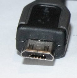
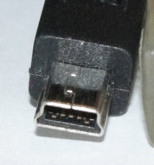
- do you have the mini usb cable plugged in next to the Ethernet port?
- unplug/replug the USB and wait 30-60 seconds
- unplug/replug the USB and power and wait 30-60 seconds (power always gets unplugged last)
- If on Windows, and without hope, try changing the COM port of the Galileo and restarting your computer.
- If working in the Galileo terminal,
- do you have the RS232 -> 3.5mm cable plugged in next to the Ethernet port?
- are you using the correct port?
- are you using the correct username / password?
Breadboard/Sensor Issues
- software,
- Is the pin mode set correctly?
- Are you using the correct pin numbers? Analog or digital?
- hardware,
- are your wires loose?
- are you using the right resistor for that sensor?
- do you actually know which cables go where?
- power,
- are the power and ground connected correctly?
- If your power columns are separated into multiple sections, are you bridging power as needed?
- If too many sensors are connected you might run out of power. Try unplugging power from some sensors.
Resetting the Galileo
- Unplug the Galileo cables connected to your computer.
- Unplug Galileo's power.
- Replug power. Wait for the one light. (Which light?)
- Replug cables. Ensure that the device port is the same.
Info Dump
IoTkit handles ethernet transactions. It connects to a host and sends a packet with [string, val] where val is the value you wish to send. You can save information locally and push it to a server later. A watch battery can be used to preserve machine state between power-on's. [validate]
There are no packages installed on Intel's Linux distro.
There's an interface for C++ that lets you access the Arduino.
Always connect the power first.
When flashing the firmware, YOU MUST HAVE THE POWER CONNECTED. Otherwise you risk bricking the board.
There are example sketches for every sensor included in Intel's sensor kit. Where? Good question.
Costs $60+ as of 2/5/14. Purchase is currently cheapest at [Micro Center] and [Amazon].
Resources
- super useful guide for getting started with the Galileo
[Technical Overview of Galileo]
- written by Arduino
- useful for getting familiar with the hardware
- good code samples
- useful for getting familiar with the software
- good code samples
- useful for getting familiar with the software
- supported software/hardware and bugs
- forum for Galileo
- Arduino-specific guide
Downloads
[Drivers]
Installation
You're impossible to please. Read the documentation from [Intel] or [Sparkfun] instead.
Research Information
These are notes and observations from research. It informs our projects, the sensors we choose, and the approaches we take.
Earthquake
- occur due to movement in tectonic plates
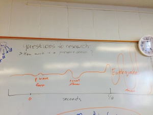
- only seconds of notice, 5-10 seconds
- [p waves] are much faster than [s waves] and the actual waves that cause the earthquake.
- earthquakes travel at about the same speed as data networks
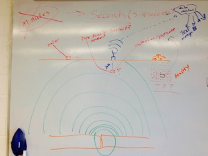
- can be measured by motion (on surface or underground) and pressure (underground)
- downside of underground monitoring is 1) power and 2) transmission
- can use repeaters or solar power to solve these issues
- advantage of being underground is distance from noise (such as animals and humans) and being closer to the source of the earthquake
- being attached to rock is good
- downside of underground monitoring is 1) power and 2) transmission
Resources
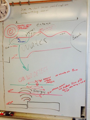
Tsunami
- in the deep sea pressure sensors are used to measure the relatively small sea-level change (in centimeters)
- nearer to shore, where waves start to form, altitude could be measured by buoy
- travel at hundreds of miles per hour
- tsunami headquarters in Hawaii
- notification could be minutes to hours in advance depending on distance from source of tsunami
- height/speed of wave reduces with distance
Code
Pins
You must specify which pin you're using to read/write to the Galileo. Declare variables for each of the pins you're using at the top of your code. It'll make life simpler.
For example use,
- const int pin_temp = A0;
- const int pin_tilt = 4;
to give your pin a useful name and to make the pin number easier to change.
Analog vs Digital
- analog pins,
- pin numbers have an "A" in front of it, like A0, A1, A2, etc
- return a range of values between 0-1023 when read from
- use values 0-255 when written to
- required for sensors that provide a range of values
- can be used as digital pins if necessary
- digital pins,
- referenced by number, like 0, 1, 2, etc
- return binary values, either 0 or 1
- can not be used as analog pins.
Setting PinMode
The pinmode ensures that you only read/write from a pin. It helps prevent bugs.
for input use,
- pinMode(pin, INPUT);
for output use,
- pinMode(pin, OUTPUT);
Read vs Write
- for analog,
- analogRead(pin)
- analogWrite(pin, value)
- for digital,
- digitalRead(pin)
- digitalWrite(pin, value)
Printing to the Serial Interface
- set serial baud rate in setup using,
- Serial.begin(9600);
- where 9600 is the rate the device and your computer will exchange information.
- write to serial using,
- Serial.print(str);
- Serial.println(str);
Hardware Specs
- 400mhz cpu
- 256mb ram
- max of 32gb micro sd
- 10/100 ethernet
- PCI Express mini-card with up to PCIe 2.0
- USB host and client
- 5v/3.3v power
- same Arduino pin layout
